
Previous
Next
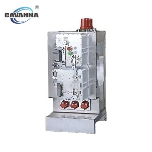
12kV Indoor Vacuum circuit breaker
These vacuum circuit breakers are designed for three phase AC 50Hz power system with rated voltages of 12/24kV, used as protection and control unit for grid equipment and power equipment of industry and mining enterprises. They are suitable for areas where frequent operations of rated operating current or multiple switching of short circuit current are required. The operating mechanism is integrated into the circuit breaker body. The circuit breaker can be installed as a fixed unit, or equipped with a truck or a withdrawable part to easily move into the switchgear.
Environmental Conditions
Environmental Conditions
- Ambient temperature: up to +40°C, greater than -15°C;
- Altitude: lower than 1000 m;
- Ambient humidity:
Daily average relative humidity: ≤ 95%;
Monthly average relative humidity: ≤ 90%;
Daily average vapor pressure: ≤2.2×10⁻³ MPa;
Monthly average vapor pressure: ≤1.8×10⁻³ MPa; - Earthquake intensity: ≤ magnitude 8;
- Areas without risks of fire, explosion, pollution, chemical corrosion and severe vibration;
Advantages
Vacuum circuit-breakers have particular advantages for use in networks where there is a high switching frequency in the working current range and/ or where a certain number of short- circuit breaking operations are expected. CA-VS1 vacuum circuit- breakers are suitable for auto reclosing and have exceptionally high operating reliability and long life. The circuit- breakers are notable for their compact design, small dimensions together with high capacity. The operating mechanisms have a low maintenance requirement and the interrupters are maintenance- free throughout their service lives. They are well suited to all load breaking operations which occur in practice, and in particular:
- Short-circuit currents;
- Overhead lines under load and, no-load conditions;
- Cables under load and no-load conditions;
- Transformers under load and no-load conditions;
- Generators under load and no-load conditions;
- Ripple control system;
- Capacitor banks(also parallel switching) and Motors with starting currents above 600A;
Technical data sheet
Rated voltage1) | kV | 12 | 24 | 36 | 40.5 | |||
Rated frequency | Hz | 50 -60 | 50 – 60 | 50 – 60 | 50 – 60 | |||
Rated normal current | A | 630…40002) | 630.25 | 630…31503) | 630…31503) | |||
Rated short-circuit breaking current (symm.) | kA | 16.31.5 | 40 | 50 | 63 | 16.31.5 | 16.4 | 16.4 |
Rated short-circuit making current | kA | 40.8 | 100 | 1254) | 158 | 40.8 | 40.1 | 40.1 |
Rated duration of short-circuit4) | s | 3 | 3 | 3 | 3 | 3 | 3 | 4 |
Fixed- / withdrawable Version | • / • | • / • | • / • | • / – | • / • | • / • | • / • | |
Max. overall dimensions (fixed Version) | mm | 150-275 | 210-275 | 210-275 | 275 | 210-275 | 280/3605) | 280/3605) |
Weight | kg | 73-105 | 94-180 | 147-260 | 265 | 100-110 | 290-365 | 290-365 |
Embedded Pole | • | • | • | • | • | • | ||
Assembled Pole | • | • | • | |||||